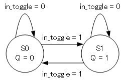
ステートマシンの実装にはムーア型とミーリ型がある。
ステートマシンの出力が現在のステートにより一義に決まるのがムーア型。
一方、ミーリ型の出力は現在のステートと、そのステートを決める入力で決まる。
具体的には、ミーリ型であればそのステートを決める入力が、ステートレジスタをバイパスして出力を決める組合せ回路にも入っている
ムーア型はハザードに強い一方、出力が1クロック遅延し、回路規模が大きくなる。
ミーリ型はその逆。
まずはt-FlipFlopを書いてみる。
- ムーア型
状態遷移図

Verilog
module t-FlipFlop_moore(
	input wire in_toggle,
	output wire q);
	//
	reg state_machine = 1'b0;
	//
	always @(in_toggle)
	begin
		if (in_toggle == 1'b1)
			state_machine <= ~state_machine;
	end
endmodule
- ミーリ型
状態遷移図

Verilog
module t-FlipFlop_mealy(
	input wire in_toggle,
	output reg q);
	//
	initial q = 1'b0;
	reg state_machine = 1'b0;
	//
	//
	always @(in_toggle)
	begin
		if ((in_toggle == 1'b1) & (state_machine == 1'b0))
		begin
			state_machine <= 1'b1;
			q <= 1'b1;
		end
		else if ((in_toggle == 1'b0) & (state_machine == 1'b1))
		begin
			state_machine <= 1'b1;
			q <= 1'b1;
		end
		else if ((in_toggle == 1'b1) & (state_machine == 1'b1))
		begin
			state_machine <= 1'b0;
			q <= 1'b0;
		end
		else
		begin
			state_machine <= 1'b0;
			q <= 1'b0;
		end
	end
endmodule
以下がRTLシミュレーションの結果である。

一番上の波形がin_toggle、2番目がムーア型t-FlipFlopの出力、3番目がミーリ型の出力だ。
ものの見事に同じだ。
次に、ボタンを0 -> 1 -> 2と順番に押していって、2を押したときに出力が出るステートマシンの例。
- ムーア型
状態遷移図

Verilog
module state_machine_test_moore(
	input wire [1:0] in_push,
	output wire out_led);
	//
	parameter STATE0 = 2'b00;
	parameter STATE1 = 2'b01;
	parameter STATE2 = 2'b10;
	parameter STATE3 = 2'b11;
	//
	reg [1:0] state_machine = STATE0;
	//
	always @(in_push[0], in_push[1], in_push[2])
	begin
		case (state_machine)
			STATE0:
				if (in_push[0] == 1'b1)
					state_machine <= STATE1;
			STATE1:
				if (in_push[1] == 1'b1)
					state_machine <= STATE2;
			STATE2:
				if (in_push[2] == 1'b1)
					state_machine <= STATE3;
			STATE3:
				state_machine <= STATE3;
			default:
				state_machine <= STATE0;
		endcase
	end
	//
	assign out_led = (state_machine == STATE3)? 1'b1: 1'b0;
endmodule
- ミーリ型
状態遷移図

Verilog
module state_machine_test_mealy(
	input wire [1:0] in_push,
	output reg out_led);
	//
	parameter STATE0 = 2'b00;
	parameter STATE1 = 2'b01;
	parameter STATE2 = 2'b10;
	parameter STATE3 = 2'b11;
	//
	initial out_led = 1'b0;
	reg [1:0] state_machine = STATE0;
	//
	always @(in_push[0], in_push[1], in_push[2])
	begin
		case (state_machine)
			STATE0:
				if (in_push[0] == 1'b1)
				begin
					state_machine <= STATE1;
					out_led <= 1'b0;
				end
				else
				begin
					state_machine <= STATE0;
					out_led <= 1'b0;
				end
			STATE1:
				if (in_push[1] == 1'b1)
				begin
					state_machine <= STATE2;
					out_led <= 1'b0;
				end
				else
				begin
					state_machine <= STATE1;
					out_led <= 1'b0;
				end
			STATE2:
				if (in_push[2] == 1'b1)
				begin
					state_machine <= STATE3;
					out_led <= 1'b1;
				end
				else
				begin
					state_machine <= STATE2;
					out_led <= 1'b0;
				end
			STATE3:
			begin
				state_machine <= STATE3;
				out_led <= 1'b1;
			end
			default:
			begin
				state_machine <= STATE0;
				out_led <= 1'b0;
			end
		endcase
	end
endmodule
こちらも同様にRTLシミュレーションをしてみた。

上から順に、in_push[2]、in_push[1]、in_push[0]、ムーア型のステートマシンの出力、ミーリ型の出力だ。
こちらもものの見事に同じになる。
はい、どう見てもVerilogではムーア型の方が書きやすいです。
(参考サイト)
http://eng.kice.tokyo/logic/trans.html
http://www.hirokinakaharaoboe.net/tips_wiki/index.php?%E7%8A%B6%E6%85%8B%E9%81%B7%E7%A7%BB%E5%9B%B3%E3%81%8B%E3%82%89%E5%9B%9E%E8%B7%AF%E3%82%92%E8%A8%AD%E8%A8%88%E3%81%99%E3%82%8B%E3%80%90Altera%20DE0%E3%80%91
http://www.hirokinakaharaoboe.net/tips_wiki/index.php?%E3%83%A0%E3%83%BC%E3%82%A2%E5%9E%8B%E3%81%AB%E3%81%99%E3%82%8B%E3%81%B9%E3%81%8D%E3%81%8B%EF%BC%9F%E3%83%9F%E3%83%BC%E3%83%AA%E5%9E%8B%E3%81%AB%E3%81%99%E3%82%8B%E3%81%B9%E3%81%8D%E3%81%8B%EF%BC%9F%E3%80%90Altera%20DE0%E3%80%91